Safety Instrumented Systems- 5 Design Tips for engineers
Free Abhisam White paper on Safety Instrumented Systems

Introduction
Modern chemical and hydrocarbon processing plants, oil & gas production facilities, power plants and other similar process plants all have some instrumentation and automation that ensures safety. These are known as Safety Instrumented Systems (SIS for short). These systems also are known by various other names such as Emergency Shutdown Systems (ESD for short), Safety Shutdown Systems, High Integrity Pressure Protection Systems (HIPPS) and so on. They may be integrated SIS DCS type of systems or separate.
But all of them belong to the class of systems that are referred to as SIS.
This Abhisam SIS whitepaper gives five important design tips when designing and building a SIS.
Designing a Safety Instrumented System
No, here we are not talking about designing the next breakthrough in a great logic solver (also commonly referred to as a “Safety PLC”). We are addressing the situation in which many Instrumentation and Control engineers find themselves in, when assigned a job to design the SIS for a process plant. Here, the entire process involves finding out what kind of systems and devices to use in the application that the client or user wants. These design tips should make the task somewhat easier.
Note: If you would want to understand the whole process completely in depth, we would suggest taking the Safety Instrumented System training course from Abhisam. It covers all aspects of Safety Instrumented systems including the entire process, starting from hazard assessment to partial stroke testing of safety shutdown valves and everything in between, including concepts such as SIL, HIPPS and all the other jargon that leaves many people intimidated and confused. Also you can get Certified as a SIS Professional for free after you take and pass our online exam.
Design Tip 1
Keep the big picture in mind. An SIS is a Risk Reduction measure, not an end in itself.
Any large processing plant has a certain degree of inherent risk that is associated with operating it. There is nothing alarming about it. The principle applies to any voluntary human activity, like say driving a car.
Driving a car has some risk and to counter this risk, one takes some safety measures (wear seat belts, have air bags, keep tire pressure OK, etc). Similarly one reduces the risk of running a process plant, by employing safety measures, one of which is by having an SIS. Thus an SIS is not the only risk reduction measure.
Secondly, the goal of any safety measure (including an SIS, is to reduce the inherent risk of a process to an acceptable level. Keep this principle in mind before jumping straightaway into SIL calculations, quad redundant PLCs, etc. Ask relevant questions such as:
Will this system reduce risk to an acceptable level?
Is this the only way to reduce the risk?
Will it work reliably always?
These are some of the questions that you should ask yourself when you are preparing the basic design.
Design Tip 2
Quantify the inherent risk and the acceptable risk.
Make sure that you know what is the inherent risk of your process (either by calculations, or historical records, or other data). This may be expressed in a variety of ways including FAR (Fatal Accident Rate), Undesired Events per year, reportable accidents per year, worker injuries per year and so on.
Now, also make sure, that you know what is the acceptable level of risk in the same units. This information can be sourced from your corporate safety department, or risk management team.
Now use the equation
Risk Reduction = Inherent Risk/Acceptable Risk
to give you a measure that will define the amount of risk reduction that your system has to be able to do.
So for example, if your process plants’ inherent risk is 1 spillage per year (of a toxic material) and your acceptable level of risk is not more than 1 spillage every 1000 years, then you need a Risk Reduction of 1000.
Hence your Safety System must be good enough for achieving a Risk Reduction of 1000.
How did we get this magic number?
Simple, we saw that Risk Reduction = Inherent Risk divided by the Acceptable Risk, which equals (1 spill/ 1 year) / ( 1 spill/ 1000 years) = (1/1)/(1/1000) = 1/0.001 = 1000.
Want to learn more calculations like this? Then take our online Safety Instrumented Systems training course.
(Scroll below to read more)
Learn about Safety Instrumented Systems including Hazard and Risk Assessment, SIL Determination & SIL Verificationin this easy online course.

Design Tip 3
Get reliability data regarding your process equipment, instruments and systems before you start the design.
There is no sense in working with assumed, or other vague figures. If at a later date, the basic data was found to be erroneous, the entire exercise of calculating target SIL, verification, etc will be pointless.
Data can be sourced from manufacturers, third party database providers or your own historical data.
The best source is, of course your own company’s historical data. However, this is easier said than done.
If you have have worked in the plant operations or maintenance department of any plant anywhere, then you realize that this is possible only when you have a sufficient number of instruments of that same make/model/type in a similar service AND your maintenance department keeps perfect records, rather than just replacing the defective ones without any record keeping.
Take the worst case figures out of the three sources, for your calculations.
(Scroll below to read more)
Design Tip 4
Keep an eye on Common Cause Failures (CCFs).
It may sound simple and ridiculous, but sometimes we fail to foresee common cause failures, even in large projects that have several hundred engineers working on it.
For example,
- Are your redundant transmitters connected to the same header?
- Are they supplied from the same bulk power supply?
- Is your BPCS and SIS powered from the same UPS?
- The same utility feeder? Could it become a CCF?
- Does your SIS card and BPCS card share a common backplane? What if the backplane fails-say due to ingress of moisture or rodents? Could it become a CCF?
Ask these questions at the design stage itself to save yourself tears later.
There was a very interesting case study on how CCFs can lay low a very expensive and technologically sophisticated program like the International Space Station (ISS). A single CCF knocked off all redundant computers in the International Space Station, endangering the lives of the astronauts. There were three redundant control computers, that carried out various functions in the ISS. However, all three were apparently commonly fed from a power line monitor, whose connectors had got corroded due to ingress of possible moisture. Thus one common power line monitor knocked off all the three control computers. Luckily the astronauts did not lose their cool and upon methodical troubleshooting found the flaw.
Take care that such a thing does not happen in your plant or facility.
Design Tip 5
Keep an eye on the SIS components, especially sensors and final control elements.
Ensure that your SIS loops do not use substandard components like cheap terminal strips, poor quality lugs, undersized signal wire and such things.
Don’t laugh, but these are real causes of failure of million dollar safety shutdown systems and HIPPs and all those sophisticated systems. Don’t be penny wise and pound foolish.
Are you aware that out of all documented failures of SIS loops, only 8% were related to the logic solvers (Safety PLCs) and fully 92% were failures related to sensors and final control elements?
Contrast this with the amount of debate, discussion and time that is spent on designing the logic solver part of the SIS (heated discussions on whether we need triple redundant safety PLCs or quad redundant safety PLCs or something even more exotic).
The reality is that very few people focus attention to the non glamorous part of the SIS loop-the transmitter and the automated valves.
Very likely they are the same types that are used in the “normal” loops. Is this a correct practice? Should not you be having a higher benchmark for these? Especially, since their performance will ultimately decide the reliability of the SIS loop?
Also be careful with your terminal strips. A poor quality termination can cause nuisance trips worth millions of dollars-have a better benchmark for these passive components in your SIS loops.
If you follow the tips above you can have definitely have a much better SIS in your plant.
If you wish to know more about Safety Instrumented Systems and associated topics such as Safety Integrity level calculations, please take a look at the Abhisam Safety Instrumented Systems e-learning course. All versions include free online testing and certification. Not only do you learn, but you get certified also and prove your knowledge and skills to your peers, bosses and clients/customers.
If you wish to get more free information like this white paper, then subscribe to our mailing list today.
Free SIS information and Whitepapers
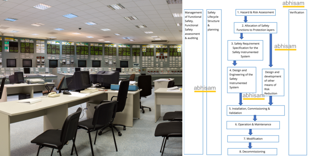
Safety Instrumented Systems- A Lifecycle approach

Safety Instrumented Systems are best designed with a lifecycle approach in mind.
Contact Us by filling the form below OR call us OR email
